

In the flavorful 1960s Eric Clapton’s signature overdriven sound with John Mayall & the Bluesbreakers gave rise to the popularization of the Marshall 1962 model amplifier. Twenty years later, sharing the stage with notable hard rock and metal guitarists gave the 80s generation of guitar players a reason to notice the almighty Marshall JCM 800s; and, keeping on a theme, in the ’90s Marshall released an updated product line of JCM900s (“900” for the 90s decade) and eventually the more recent JCM2000s.
In this post, we will be looking at the variations of the tone stack circuitry in Marshall’s early product lines. We’ll go from the 1962 Bluesbreaker model all the way up to the JCM900 Dual Reverbs.
While the basic tone stack topology is relatively common throughout the Marshall lineage, each vintage has its own characteristics that makes it work with their corresponding design changes.

Disclaimer: Stompbox Electronics and/or the author of this article is/are not responsible for any mishaps that occur as a result of applying this content.
The Benchmark – Marshall 1962 Combo “Bluebreaker” Reissue
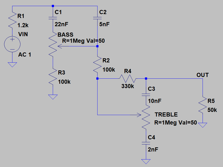
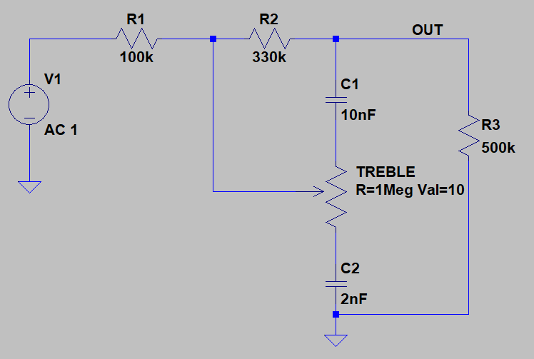
The first model we’ll take a look at is the famous “Bluesbreaker” 1962 Combo (Reissue). Figure 1a shows the tone stack circuit. For the sake of consistency we’ll be using an input resistance value of 1.2k and a load resistance of 500k for all of our samples.
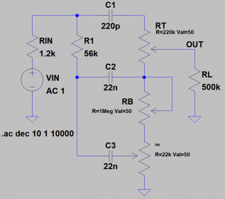
The exact circuit operation is best saved for another post. For now we’re only concerned with how the component differences between each model affects the tonal response of the amplifier.
Since I’m introducing the 1962 first we will use this as our benchmark example.
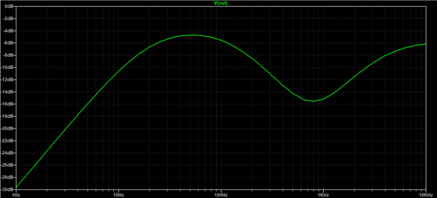
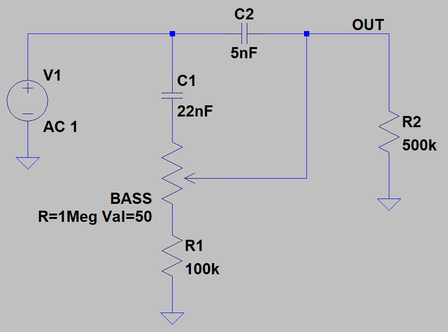
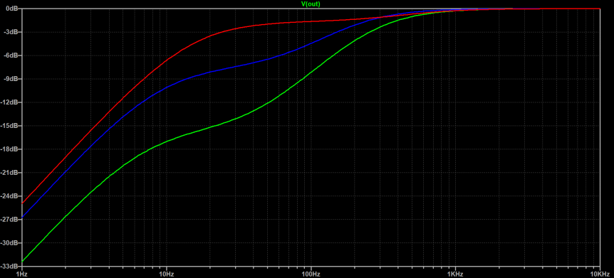
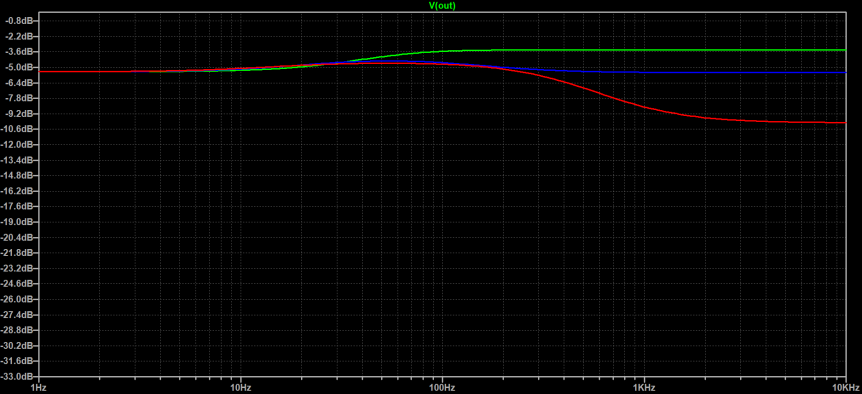
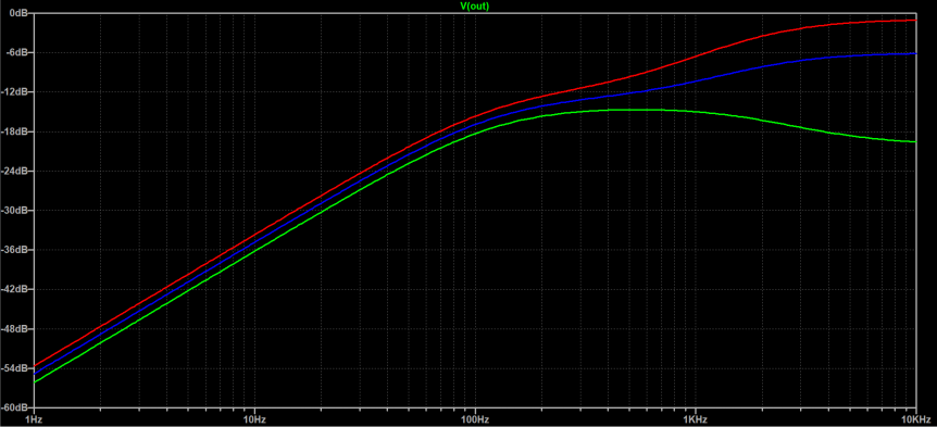
I’ve plotted the frequency response with the wipers of all pots at 50% for comparison with other tone stacks (Figure 1b).
Note that the best way to compare each tone stack is to build the circuit and play through it. Unfortunately I don’t have thousands of dollars to spare, so the easiest way for me to compare is to set everything to 50% and compare them by visualizing their frequency responses in LTSpice.
A great web resource for this is the Tone Stack Calculator on Guitar Science’s site. This resource is good for the standard tone stack topology, but some of the versions stray away from the standard so I’ll be presenting fixed responses generated by LTSpice (like in Figure 1b).
Marshall JCM Series
JCM800 2203 & 2204
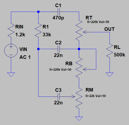
Next up are the 2203 & 2204 models. Figure 2a show the tone stack circuit we’ll be working with here. These particular component values are used in both the JCM800 2203 and the JCM800 2204, as well as the JCM900 2500 Master Volume.
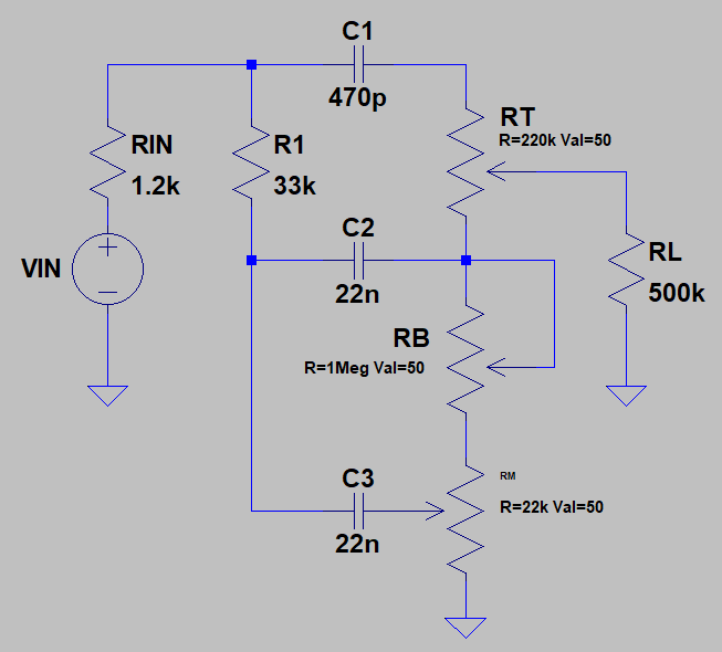
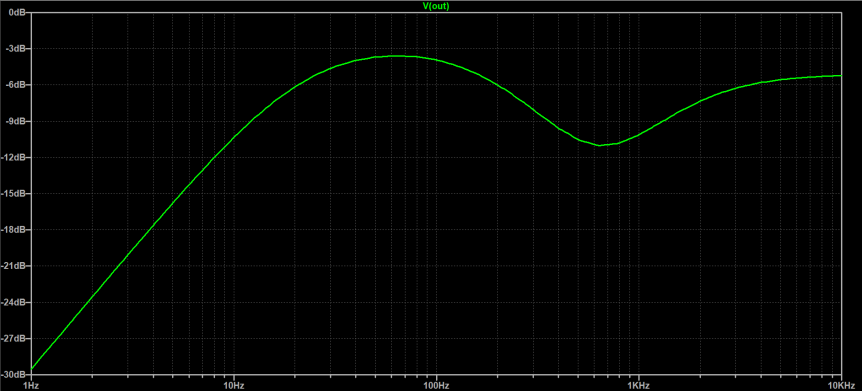
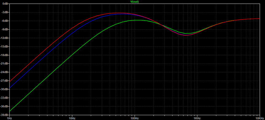
The two most influential changes in the design involve C1 (270pF to 470pF) and R1 (56k to 33k). The plot shown in Figure 2b shows how the component values affect the response of these early JCM800s.
Let’s take a more detailed look at how these changes affect the circuit…
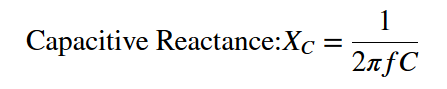
Capacitive Reactance
Capacitive Reactance (Xc) is the frequency-dependent “resistance” or “impedance” of a capacitor to a signal.
From Equation 1 we know that capacitive reactance is inversely proportional to the capacitor’s capacitance (C). It’s also inversely proportial to the frequency (f) of the signal passing through it.
If the frequency of the signal is relatively high, the capacitive reactance (resistance to the signal) will be low. And if the capacitive reactance is low, the signal will be allowed to pass through it.
On the other hand, if the frequency of the signal is relatively low then the capacitive reactance will be high. Thus, the capacitor does not allow the signal to pass.
Bluesbreaker vs. JCM 2203/4 Tone Stack Differences
With that, we now have a general idea of what changing any of the capacitor values will do to the circuit. Changing C1 will affect the Treble response, C2 the Bass response, and C3 the Mids response.
By increasing C1 from 270pF to 470pF we can expect a 2203/2204 tone stack to have the ability to pass a larger amount of lows than the Bluesbreaker stack due to the overall decrease in capacitive reactance in that branch.
As for the change in R1’s value, the exact calculations behind this are out of the scope of this article. Decreasing the size of this resistor allows more of the signal into the Bass and Mids filter stacks. By decreasing R1 the signal passing through the 2203/4s has more presence in the Mids and Bass ranges than the Bluesbreaker design.
If the resistance would have increased, however, then the impedance of that branch would also increase and would generally let less of the signal into the Bass and Mids filter stacks, resulting in less presence in those frequency bands.
JCM800 2210 Tone Stacks
Next up: the JCM800 2210! With the release of this unit Marshall was just starting to venture into the multi-channel realm.
The 2210 has two channels (Normal and Boost) each with their respective tone stacks. The Normal channel tone stack (Figure 3a) has only two (2) treble and bass controls, while the Boost channel sports a three-band EQ (Figure 4a, below).
Both of these tone stacks are quite different, and both stray away from the stacks utilized in the 1962 and 2203/2204 models.
JCM800 2210 Normal Channel Tone Stack
The Normal channel hosts two shelving filters cascaded together. First, the signal passes through a High-Pass shelf where the Bass pot controls the depth of the shelf in the lower frequency range.
Figure 3c shows you the tonal response of this first filter stage with the Bass pot turned to 10%, 50% and 90% of its value.
Figure 3b shows the model used for the first filter stage. At 10% there is a deeper roll-off with a small shelving effect. This shelf increases in range as we increase the pot value from 10% to 90%, all while the roll-off becomes more and more gradual.
After passing through the first filter, the signal is then fed directly into another passive filter sharing a similar shelving effect, only this time in the treble frequencies.
The frequency response in Figure 3e (below) applies only to the second filter stage (as modeled in Figure 3d).
In this plot you can see how the treble frequency response moves in relation to the Treble pot position. A bleed into the mids is also evident, so this filter affects both the Mids and Treble response.
JCM800 2210 Boost Channel Tone Stack
Onto the Boost channel!
The Boost channel hosts a three-band EQ (Figure 4a), but one that differs from the traditional Marshall Tone Stack we saw in the 1962 and the previous JCM800s.
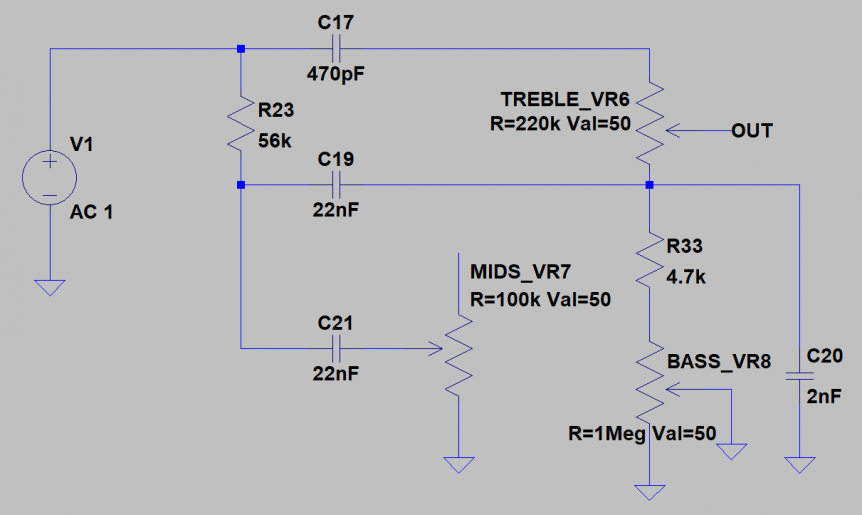
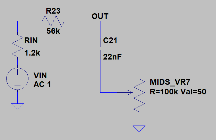
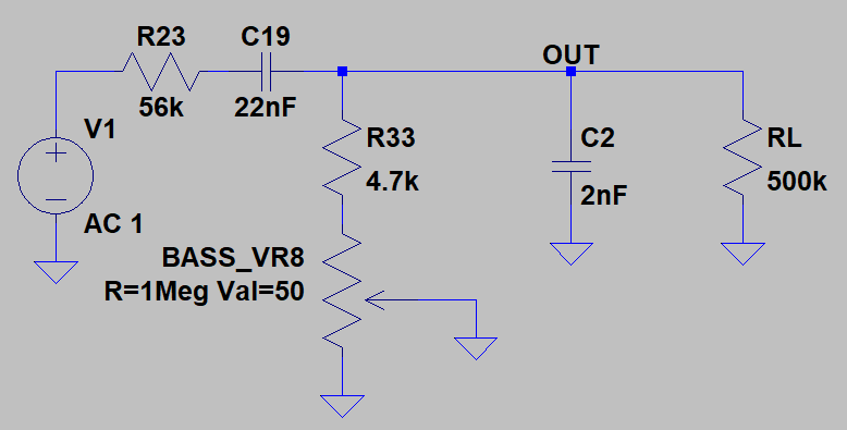
In this case, you can sort of think of this stack as a two-stage filter. The first stage is a low-pass shelving filter for the Mids (formed by R23, C21, and VR7). The output of that filter cascades into the (relatively complicated!) two-band filter responsible for the Bass and Treble response.
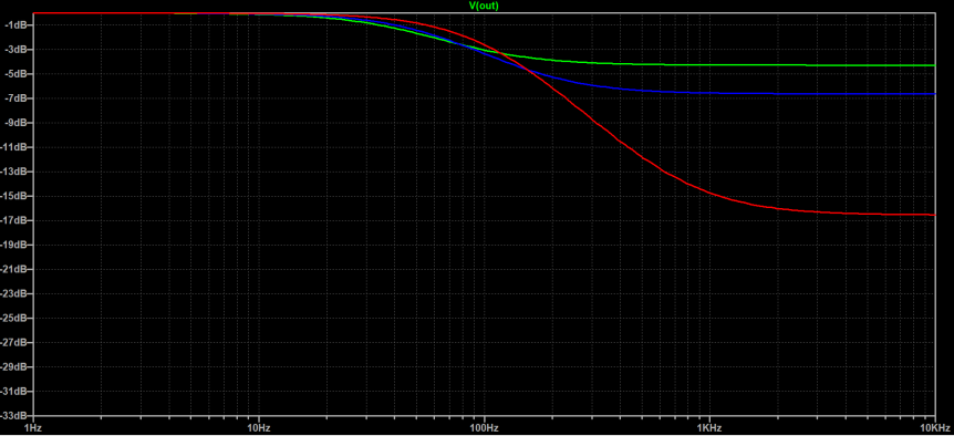
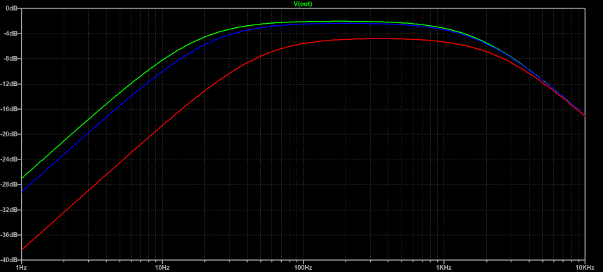
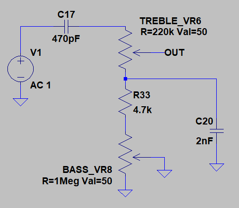
Moving on, let’s look at the bass reponse. The Bass response is dictated by a band-pass filter formed by R23, C19, R33, VR8, and C20 (Figure 4d). The Treble response is dictated by C17, VR6, R33, VR8, and C20 (Figure 4f). Their plots can be seen below in Figures 4e and 4g, respectively.
From Figure 4e we can say that the position of VR8 (i.e. the Bass control) affects the Treble response.
JCM900 2100 SL-X
The JCM900s are split between two main product ranges: the SL-X and the Dual Reverbs.
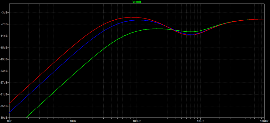
Initially we’ll look at the SL-X (the 2100 SL-X) which has a tone stack similar to the JCM800 2203/2204. The only difference is that the 1Meg Bass potentiometer has been swapped for 220k, as seen in Figure 5a.
This change drastically lowers the Bass response, along with its control range. However, the SL-X Master Volumes are known for introducing a third ECC83 valve in the gain stage, so this may be a result of the pre-amp’s design change.
Figure 5b shows plots with the bass potentiometer at 1Meg. The plot in Figure 5c shows the bass potentiometer being 220k.
JCM900 4100 Dual Reverb
For the Dual Reverb’s master EQ controls, Marshall went back to the 800 roots and inserted the same design from the 2203/2204 models. However if we look closely there is one more non-adjustable Boost Pre-EQ stack in the preamp circuit (Figure 6a).
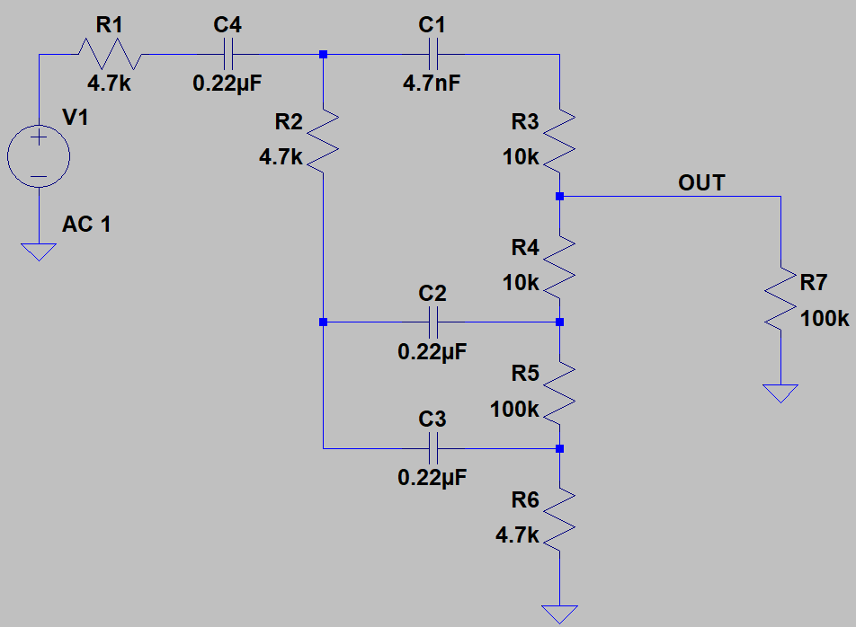
These values widely differ from the previous stacks we’ve seen. Simulating these values indicates that the bass and treble frequencies become accentuated with a dip in the low-mids (Figure 6b).
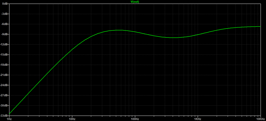
Since this frequency response is fixed, it would be interesting to see if this Pre-EQ stack can be modified to affect the signal going into the clipping stage.
Meet the Author:

Hi, I’m Dominic. By day, I’m an engineer. By night, I repair and modify guitar effects! Since 2017, I’ve been independently modifying and repairing guitar effects and audio equipment under Mimmotronics Effects in Western New York. After coming out with a series of guitar effects development boards, I decided the next step is to support that community through content on what I’ve learned through the years. Writing about electronics gives me great joy, particularly because I love seeing what others do with the knowledge they gain about guitar effects and audio circuits. Feel free to reach out using the contact form!
The Tools I Use
As a member of Amazon Associates, Stompbox Electronics earns and is supported by qualifying purchases.


