Welcome to Part Three of this multi-part series on Passive Filters!
In Part 1 we went over preliminary information to go about analyzing and designing passive filter circuits. That information isn’t required for basic filter design but it is required for designing and analyzing more complex filters, so it would be a good idea to run through those topics. In Part 2 we discussed the basic RC Low-Pass and High-Pass filters and how to design them for a specific cut-off frequency.
In Part 3 we’ll be taking a more exploratory path. I call the following four filter designs “Modified” RC Filters because they are technically modifications of the simple RC filters covered in Part 2. There are four main types I’ve come up with: (I) RC-R, (II) RC-C, (III) R-CR, and (IV) C-CR.
Type I (RC-R) and Type III (R-CR) are high-pass and low-pass filters, respectively. A resistor is placed in series with the capacitor, which works to attenuate the passband by a fixed amount.
Type II (RC-C) and Type IV (C-CR) are low-pass and high-pass filters, respectively. A capacitor is placed in series with the resistor, which can be used to alter the attenuation of the stopband. The passband level is kept constant with 0 dB attenuation.
Type I: RC-R
Type I: RC-R consists of a resistor and capacitor in the upper branch and one resistor in the lower branch (Figure 1).
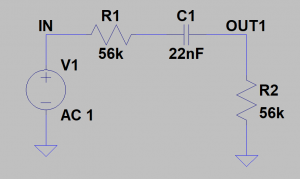
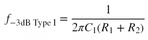
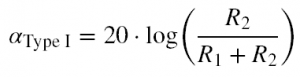
This filter is high-pass (since the capacitor is in the upper branch) and has a cut-off frequency given by Equation 1. If R1 is set to zero then the RC high-pass filter seen in Part 2 of this series is formed. (In a way, this can be seen as a special case of this Type 1 RC-R filter.) As the resistance of R1 increases, the pass-band starts to attenuate in accordance with Equation 2 (given in dB).
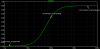
As an example, set R1 and R2 to 56k and C1 to 22nF. Figure 2 shows the simulated result, with a cut-off frequency of ~64 Hz and a pass-band attenuation of -6 dB.
Type II: RC-C
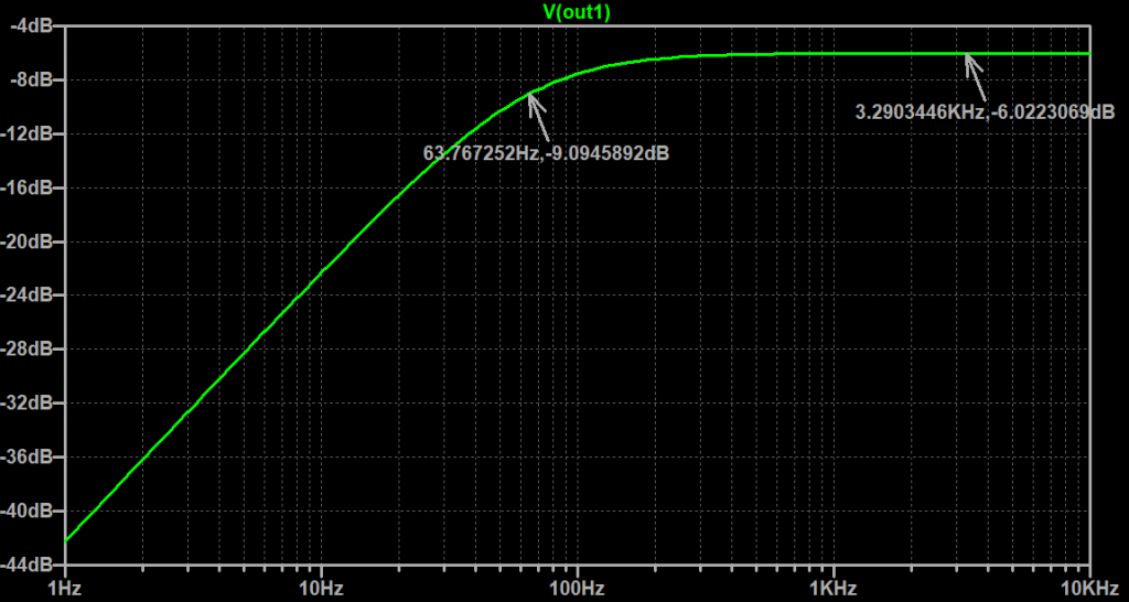
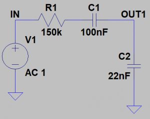
Type II: RC-C filters (Figure 3) have a low-pass characteristic. The series capacitor added to the top branch acts to proportionally block lows and allows the designer to set an attenuated level in the passband.
Type III: R-CR
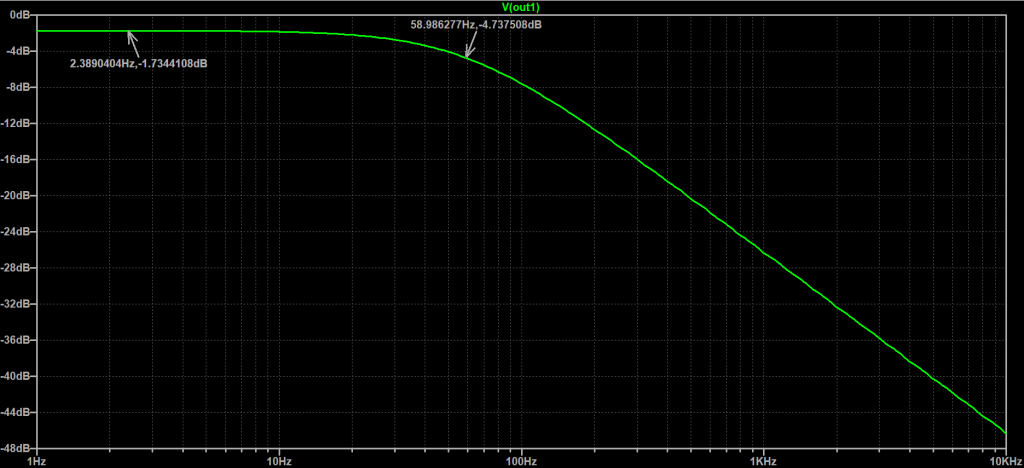
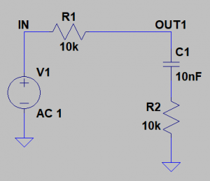
Type III: R-CR filters consist of a resistor in the upper branch and a capacitor and resistor in the lower branch (Figure 5).
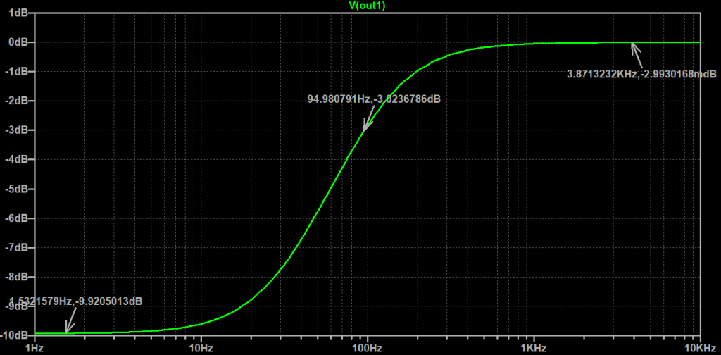
These Type III: R-CR filters have a low-pass characteristic. Instead of attenuating the passband, these filters allow for an adjustment of stopband attenuation. This essentially allows you to cut highs to a lesser degree than if you were to use a normal RC Filter described in Part 2 of this series. As such, this provides a shelving effect and can be very useful for simple passive audio filters.
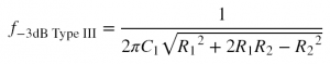
The equation for finding the cut-off frequency for Type III R-CR filters is derived to be Equation 5. It is possible, though, for R2 to get so large in comparison to R1 such that levels higher than -3dB are realized, in which case this equation will not give you a sensible result.
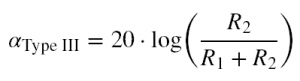
The amount of attenuation in the stop-band can be calculated by Equation 6, which is identical to that of Type I RC-R filters. See Figure 6 for the frequency response of the circuit in Figure 5.
Type IV: C-CR
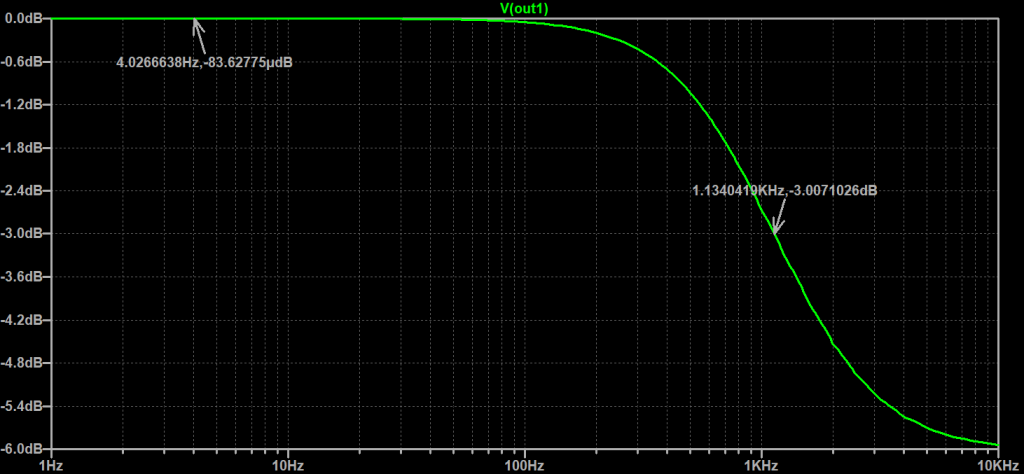
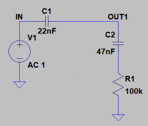
Last, but not least, Type IV: C-CR filters! These have a high-pass characteristic and provide a shelving effect similar to the Type III filters above. Figure 7 provides an example:
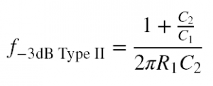
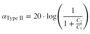
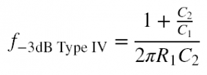
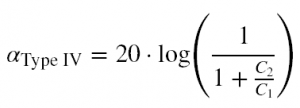
Calculate the -3dB frequency by using Equation 7 and the shelf attenuation level using Equation 8. In the case that the shelf level is above -3dB (when C2 becomes large with respect to C1), equation 8 seems to give a sort of “alpha/2 dB” level where the frequency starts corresponding to the point at which the response is half of the shelf attenuation. It’s interesting and unexpected, but renders values where that occurs useless for our purposes.
Note, also, that Equation 7 and Equation 8 are identical to those of the Type II: RC-C filter.
Wrap-Up
So far we’ve covered basic passive filters and I’ve even gone so far as to modify them for shelving filter applications. The reason I took this route for Part 3 is simply because a lot of tone stacks rely on the interaction between multiple capacitors and resistors to form their frequency responses.
In Part 4 we’ll go over the passive RC band-pass and band-stop filters.
Stay Tuned!
-Mimmo