The Low-Pass Filter
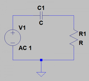
First up is the passive RC Low-Pass filter (shown in Figure 1). It’s composed of a resistor (R1) and a capacitor (C1), as expected. The capacitor is the component we see connected to ground, which is a key indicator to look for when searching for passive low-pass filters in audio circuit schematics.
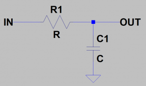
Those with basic electronics knowledge may be able to recognize this topology as similar to the voltage divider, except instead of two resistors we have a capacitor on the bottom half of the circuit.
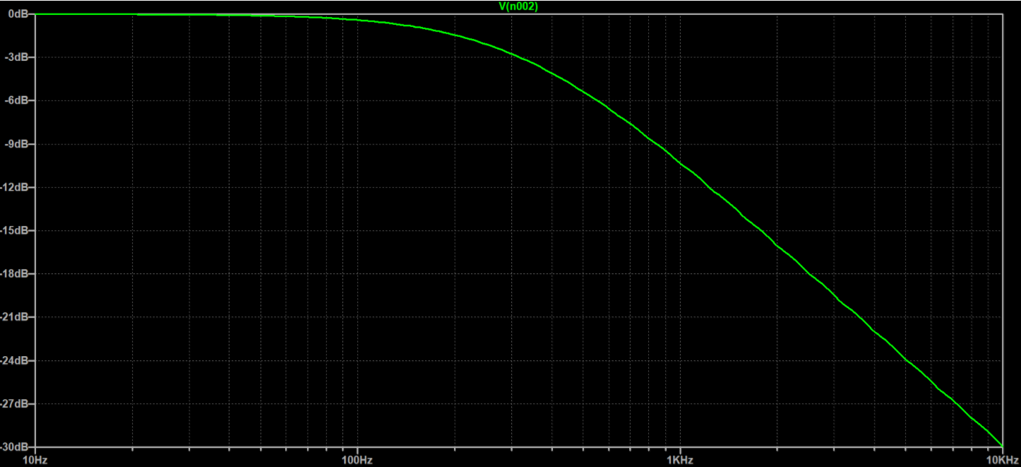
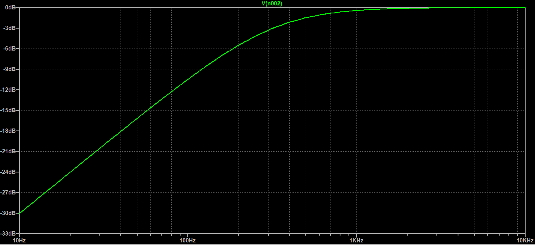
I’m a believer in teaching by example, so let’s sub in a 50kohm for R and 10nF for C. The circuit’s simulated frequency response (from 10Hz to 10kHz) is shown in Figure 2. Here we see a shelf of 0dB (unity gain) for frequencies below about 60Hz. After 60Hz we start to see slight attenuation until eventually the drop in attenuation looks linear on a log-scale.
The -3dB Frequency
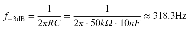
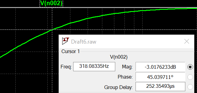
Let’s define the -3dB frequency (also called the cut-off frequency, knee frequency, etc.). The -3dB frequency is the frequency at which the signal attenuates by 3dB, or 0.707 times the signal’s max voltage amplitude. In terms of power, this translates to the frequency at which half the maximum power is found in the signal. The formula in Equation 1 can help you determine the -3dB frequency of a passive RC low-pass filter.
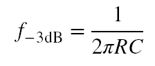
Generally, if you want to build a low-pass filter, you usually start with Equation 1. If you were to substitute the resistor for a variable resistance, you would use this equation to determine ballpark component values based on a desired frequency range.
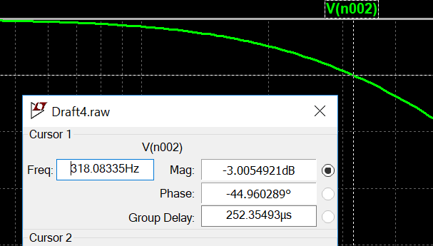
Turning our attention back to our example and subbing the values into Equation 1 we can obtain our calculated -3dB frequency (Equation 2). Checking back to our plot in Figure 2, we see that the formula works.
Your experience may vary when using this formula in the real world. Component tolerances are their values to vary relatively largely, which is why it’s always advisable to design filters with components having tight tolerances. For now, that is all we really need to go over for the passive low-pass filter. Other passive filter topics like Roll-Off and Filter Ordering will be reserved for a future post.
The High-Pass Filter
Next up: the passive RC High-Pass filter (shown in Figure 4). Again, it is composed of a resistor R1 and capacitor C1. Note that this time the resistor is connected to ground: another key indicator to look for when inspecting audio schematics.
Let’s do like we did before and substitute 50k for R and 10nF for C. Putting that through a simulation we get the plot in Figure 5. We see the output contains high-frequency content with the low frequencies mostly attenuated.
What’s more? The -3dB frequency ends up being the same as the Low-Pass configuration. That’s right, take a look at Figure 6. The equation to solve for the -3dB frequency (Equation 1) doesn’t change between the Low-Pass and High-Pass Passive RC filter configurations. That, sir, is great news!
That’s all for this post! In Part 3 we will start expanding on these basic circuits with a type of filter called a shelving filter.