Filters are used literally everywhere in electronics… They’re used for decoding communication lines, tuning your radios, and (most importantly) making sure your tone is absolutely killer! You can build basic filters very cheaply, with just a couple of components.
In this multi-part series we’ll be looking at filters made up of capacitors and resistors, and in this article we’ll start out with the preliminary knowledge required to go about analyzing an RC filter. All this preliminary stuff is required to go about analyzing passive filters. Most of us want to design filters, though… We will start to design basic passive filters in Part 2 of this series. In Part 3 we will expand on that article and discuss passive shelving filters.
What are Passive Filters?
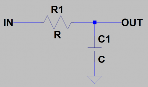
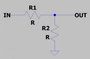
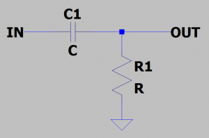
A passive filter is a filter built from passive components (i.e. capacitors, resistors, or inductors). Inductors are relatively expensive, so we’re going to skip them entirely and only focus building filters from capacitors and resistors. Figure 1 shows the prime example of a passive Low-Pass Filter. In this topology, the capacitor is connected to ground while the resistor is in the signal path. The output is taken from the node between the resistor and capacitor.
FIGURE 1: Low-Pass Filter circuit topology.
Those with electronics knowledge may be able to recognize this topology as similar to the voltage divider, except instead of two resistors we have a capacitor on the bottom half of the circuit. We are using a capacitor because it has a property called reactance.
What is reactance you say?
Capacitive Reactance
Let’s take a look at resistance. Resistance comes with a very straight-forward concept. If you put something with resistance in the way of an electric current then that resistance will, by Ohm’s Law, resist the electric current. Increasing the resistance in a branch will decrease the current’s ability to flow and vice-versa.
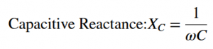
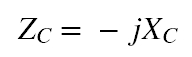
One important attribute that resistors lack is frequency-dependence. For all intents and purposes, the resistor doesn’t care if you, the signal, are 100 Hz or 100kHz, it will resist you with no discrimination. Capacitors, on the other hand, are very frequency-dependent components, and the way we measure their “resistance” to a particular frequency is through a parameter called capacitive reactance.
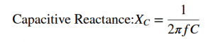
EQUATION 1: Reactance of a capacitor.
Capacitive Reactance (Xc) is a calculated value which is inversely proportional to the capacitance (C) of the capacitor and the frequency (f) of the signal passing through it, as seen in Equation 1. Generally, a capacitor with twice as much capacitance will have half the amount of capacitive reactance to a particular frequency. This frequency dependence makes capacitors extremely attractive in the design of analog filters!
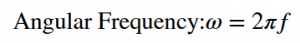
Sometimes (2*pi*f) is substituted for omega, or angular frequency, which is expressed in Equation 2. There’s a mathese reason for this, but it’s best to just think of this as a simple mathematical substitution for our purposes. It also makes equations easier to deal with, so embrace this with an open mind.
Equation 2: Angular Frequency definition
With that in mind, most of the time we’ll see capacitive reactance referred to as in Equation 3 (below). This will become important later on when we start getting down and dirty deriving the filter equations.
Equation 3: Capacitive Reactance expressed with omega.
Impedance
An important distinction needs to be made before we move on…we need to talk about impedance. Resistors are components with resistance, but no reactance. Theoretically, capacitors have reactance, but no resistance. To analyze a circuit with both resistive and reactive elements (like filters…) we need to speak in terms of impedance.
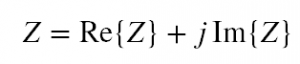
Equation 4: Impedance as Real and Complex.
Impedance is a complex number (Equation 4), with its real part identifying the resistive characteristic of a circuit and it’s imaginary part identifying the reactive characteristic. Impedance gives you the whole picture for how much, and in what way, a circuit element will impede any signal applied to it. If you’re able to find the impedance, you’re able to at least start analyzing the circuit at hand.
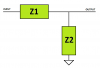
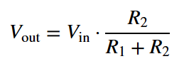
Take a look at the abstract circuit in Figure 2, Z1 and Z2 represent the impedance of two components. They could be resistors, capacitors, inductors, or a mix between the three. Let’s say they’re both resistors; that means both Z1 and Z2 have a purely resistive quality to them. In that case, it’s appropriate to substitute R1 for Z1 and R2 for Z2. This is our old friend, the voltage divider (Figure 3).
FIGURE 2: Abstract circuit with component 1 having impedance Z1 and component 2 having impedance Z2.
FIGURE 3: Resistive voltage divider circuit.
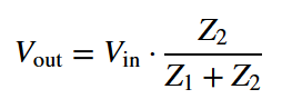
Now let’s look at Equation 5: this is the voltage divider formula derived from purely resistive components. Once we take into account impedance and swap the R’s for Z’s we get Equation 6, which is a complex voltage divider formula. This formula allows us to determine the “complex” output voltage of the circuit due to the impedance of the components making up Z1 and Z2. It’s the exact same concept as the original voltage divider, except now we can see how adding a capacitor will affect the output signal of the circuit.
EQUATION 5: Voltage Divider Formula
EQUATION 6: Complex Voltage Divider Formula
Turning the attention to Figure 2: Instead of Z1 and Z2 both being resistors, let’s place a resistor into Z1’s spot and a capacitor into Z2’s spot. This is the low-pass filter circuit we showed in Figure 1! And if we had instead placed a capacitor into Z1’s spot and a resistor into Z2’s spot we would obtain the circuit for a high-pass filter (Figure 4). We’ll use both of these filter topologies in Part 2 when we get an in-depth look into how these filters work.
FIGURE 4 High-Pass Filter circuit topology.
Bringing it back to Equations 5 and 6, the reason we were able to swap out the R’s for Z’s is because the impedance of a resistor is simply it’s resistance. Therefore, it’s a simple, straight-forward substitution. What we haven’t seen is the impedance of a capacitor. Due to the limited information I can bring into a blog post, I would rather give this to you than explain it so…Equation 7 is the impedance of a capacitor.
EQUATION 7: Impedance of a capacitor.
Working with Complex Numbers
This section walks you through a basic example for the sole purpose of learning how to work with complex numbers. Since complex numbers can be used to separate resistive and reactive properties, it would help to know how to work with them. Math is great and all, but we won’t go into too much detail since most of the material on working with complex numbers is already well-documented and available elsewhere on the web. For our purposes we will only look into what we’ll need to get through this series.
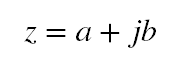
Refer to Equation 8 below. The variable “a” denotes the Real component and the variable “b” denotes the Imaginary component, which is always accompanied by the imaginary number “j”. The imaginary number “j” has some special properties that can be read up on elsewhere (Wikipedia).
EQUATION 8: Standard form of a complex number, z.
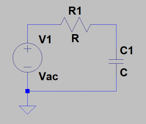
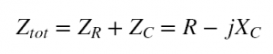
Now let’s take the circuit in Figure 5 as our example. We have a signal source, Vac, which is fed into a branch with a resistor and capacitor in series. The resistor has resistance, R, and the capacitor has capacitance, C. The total impedance of the branch needs to expressed as a complex number since both resistive and reactive components are present. This gives us Equation 9, expressing the total series impedance of the branch.
FIGURE 5: Resistor and Capacitor in series.
EQUATION 9: Working out Figure 5’s total series impedance.
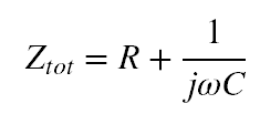
Remember how I said that “j” had some special properties? One of them is the ability to convert itself from -j to 1/j. That property is the most important one to remember here, and one that has extreme importance on simplifying the math. With that property, along with the definition for capacitive reactance, we get Equation 10.
EQUATION 10: Total impedance of branch circuit in Figure 5.
Complex s-Notation
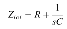
A lot of things are done in the name of simplification. Mainly because math is tedious… One of the best tools for simplifying filter equations is the use of complex s-Notation. All we do is substitute “s” for “j-omega”, like we’ve done in Equation 11. This only becomes relevant when the equations are derived for low-pass and high-pass filters.
EQUATION 11: Total impedance expressed with s-Notation.
Magnitude of a Complex Number
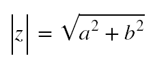
Next up is how to find what’s called the “Magnitude” of a complex number. Refer to Equation 8 with the “a” and “b” designations. The formula for finding out the magnitude from that form is shown in Equation 12 below. This, too, is relevant….bare with me and wait for the follow-up posts for this to be useful.
EQUATION 12: Magnitude of a Complex Number.
Conclusion
We got through a lot there, and I hope that was enough to keep you busy. To sum it all up, we went over:
How to find the impedance of a resistor.
How to find the impedance of a capacitor (Equation 7).
How to find the impedance of a circuit branch.
Understanding s-Notation.
How to find the Magnitude of a Complex Number
Of course, not all of this is needed to build filters…but it is required to work out and understand how complex ones work (pun intended). The simple Low-Pass and High-Pass RC filters we will be going over in the next article are relatively easy to understand, and can be tackled without the excessive math. For more complex tone-stacks, however, these tools are necessary to understand the mechanisms for how they work.