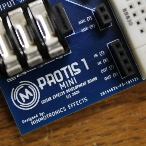
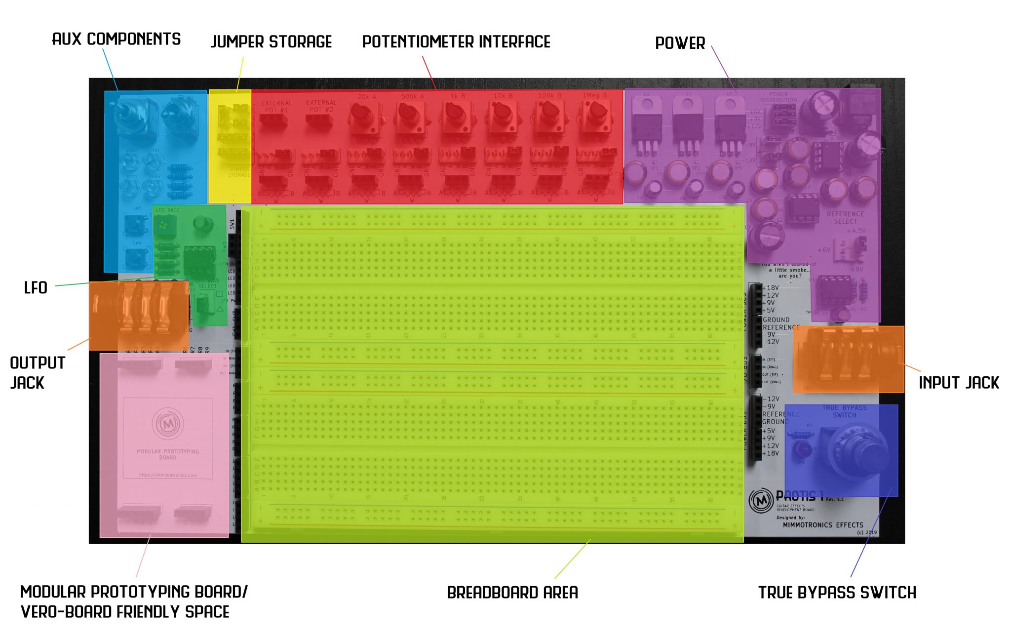
PROTIS 1 Guitar Effects Development Board

The Mimmotronics’ PROTIS 1 is the premier Guitar Effects Development Board for DIY pedal builders and enthusiasts.

  • Organize and stream-line your design experience.
  • No need for constructing repetitive power and input/output wiring.
  • Expand your prototyping with Prototyping Module Boards.

PROTIS 1 Features

  • 1,560-point breadboard prototyping space
  • Input and Output jacks for guitar and amplifier testing
  • On-board positive and negative power options
  • True Bypass switching for easy on/off floor testing with other effects chains
  • Six (6) on-board potentiometers, two (2) tactile switches, and two (2) toggle switches
  • Low-Frequency Oscillator (LFO) ranging in oscillation frequency from 0.5 to 20 Hz
  • Propped up from the bench surface with six (6) rubber feet
  • Modular Prototyping Board space for customizing your prototyping experience.
  • [Optional] 18VDC Power Supply
  • [Optional] Male-Male prototyping jumper wires

I. Power

The PROTIS 1 hosts four (4) power rails (+18V, +12V, +9V and +5V), the latter three are made live by removable jumpers.

The +12V and +9V rails have their inverted counterparts (-12V and -9V) which are made available by their respective jumpers.

The power can be be enabled using jumper shunts at the top right of the prototyping board.

Half-voltage DC biasing for single-supply circuits is accessed by configuring the REFERENCE SELECT jumpers.

Power is easily accessible from the female headers to the right of the breadboarding space.

PROTIS 1 power bus headers for connection to positive and negative voltage rails, ground, and reference voltage.

***Recommended Power Supply: +18V DC power supply, 500mA. This can also be provided by 18VDC pedal power bricks, like the Voodoo Labs ISO 5, for example.

II. Signal Flow

Signal flow is identical to how it works in most pedals: right to left! The guitar’s input signal is applied to the right-side 1/4″ jack and the output is taken from the left-side 1/4″ jack.

A 3PDT footswitch switch in the lower-right hand corner of the board carries out True-Bypass operation. The LED next to the switch serves as an indicator for when the breadboarded circuit is “engaged” (ON) or “disengaged” (OFF).

Input and output signals are located in headers to the left and right of the prototyping board space. The 3PDT footswitch allows you to switch between true bypass and the FX signal on the breadboard.

When the circuit is “ON” the input and output jack’s Tip signals are routed to the Signal I/O headers on the left and right sides of the breadboarding space. The input guitar signal and output FX signal can be connected to the breadboard using jumper wires from the I/O headers.

Stereo effects can also be developed using the PROTIS 1 by utilizing the “ring” connections on the I/O headers. Do note, however, these ring connections are not switched on or off by the 3PDT switch, only the tip connections.

III. Potentiometer Interface

Six (6) On-Board Potentiometers are available for use on the PROTIS 1:

  • Four (4) linear B-type (1kB, 10kB, 100kB, and 1MB)
  • Two (2) log A-type (20kA, 500kA)

Pot Interface Jumper Configurations allow you to minimize the wiring needed for using potentiometer.

Two sections are reserved for the Connection of External Potentiometers in the case that the PROTIS 1 does not house the value you need for the circuit at hand. 

The potentiometer space is fitted with 6 on-board potentiometer values: 1kB, 10kB, 100kB, 1MB, 20kA, and 500kA. There are two areas where you can connect external potentiometers, in case the board doesn't have the values you need.

IV. Auxiliary Devices

The PROTIS 1 offers four (4) auxiliary devices, including:

  • Four (4) LEDs: Green, Yellow, Orange and Red (current-limited with a 1k-Ohm resistor)
  • An SPDT ON-ON toggle switch
  • A DPDT ON-OFF-ON toggle switch
  • Two (2) momentary tactile push-buttons
  • One (1) Low-Frequency Oscillator (LFO) with a range of 0.5 Hz to 20 Hz.

Each of these devices are accessed by the corresponding headers along the left side of the breadboard prototyping space.

An area for storing un-used jumpers/shunts is available just next to the external poteniometer area to serve for a cleaner bench space.

The PROTIS 1 includes LEDs, two toggle switches (one SPDT and one DPDT) and two tactile pushbutton switches. There is also a space on the board to store un-used jumpers/shunts.

V. Modular Prototyping Boards

The PROTIS 1 provides the ability to customize your prototyping experience by allowing the ability to add Modular Prototyping Boards.

The design is adapted to be protoboard-friendly with 2.54mm lead spacing. Mimmotronics-designed Module Boards are also available.

Support Posts